The Mule rides again (sort of) - pics.
Moderators: The Dark Side of Will, Series8217
-
The Dark Side of Will
- Peer Mediator
- Posts: 15637
- Joined: Wed Nov 24, 2004 11:13 pm
- Location: In the darkness, where fear and knowing are one
- Contact:
Re: The Mule rides again (sort of) - pics.
Steel on steel ball joint or rubber bushing? I'm looking for steel on steel.
-
CincinnatiFiero
- Posts: 2908
- Joined: Thu Dec 20, 2007 2:47 pm
- Location: Columbus, Ohio
Re: The Mule rides again (sort of) - pics.
They are steel on steel. I chilling at my house just had wisdom teeth surgery so I'm not hitting the shop today.

-
The Dark Side of Will
- Peer Mediator
- Posts: 15637
- Joined: Wed Nov 24, 2004 11:13 pm
- Location: In the darkness, where fear and knowing are one
- Contact:
Re: The Mule rides again (sort of) - pics.
Thanks!
I pulled the PN out of the URL. I assume 2203520227 is the Merc PN?
And these guys show the Lemforder PN (34756-01): http://www.europartimports.com/catalog/ ... ucts_id=32
Which leads me to Lemforder's catalog page (was just there looking up BMW 325iX ball joints):
http://webcat-services.zf.com/index.asp ... ,1632,1614
But at an outer diameter of 40mm, it's unfortunately too big. I need something ~30mm or less.
-
The Dark Side of Will
- Peer Mediator
- Posts: 15637
- Joined: Wed Nov 24, 2004 11:13 pm
- Location: In the darkness, where fear and knowing are one
- Contact:
Re: The Mule rides again (sort of) - pics.
Oh yeah, sorry to hear that. Wisdom tooth surgery sucks. I had all four of mine out at once in college. I was hurtin' for a while.CincinnatiFiero wrote:They are steel on steel. I chilling at my house just had wisdom teeth surgery so I'm not hitting the shop today.
-
CincinnatiFiero
- Posts: 2908
- Joined: Thu Dec 20, 2007 2:47 pm
- Location: Columbus, Ohio
Re: The Mule rides again (sort of) - pics.
I'm in college and had all four taken out at the same time lol.
It sucks, but having a crappy weekend is better than all the problems they can cause eventually.
I've seen those style "bushings" on lots of BMWs and Mercedes so there is probably a reasonably priced off the shelf one out there somewhere.
I'll look at that bushing when I go back up to Columbus, I'm trying to think if other Benzes use the same setup but maybe a different bushing. The problem is 220 is a 2000+ S-class so if the P/N has superseded all the way up to a car they made until '07 the vast majority of 80s,90s,and early 2000 Benzes probably take the same part.
Do not know if you are aware but 9 times out of 10 the first three numbers of a Mercedes p/n are either a chassis number or the engine code. So a 220-XXX-XXXX bushing will definitely fit a W220 S-Class, but does fit other models. If it starts with 000 its probably a tool, or something very generic.
-
The Dark Side of Will
- Peer Mediator
- Posts: 15637
- Joined: Wed Nov 24, 2004 11:13 pm
- Location: In the darkness, where fear and knowing are one
- Contact:
Re: The Mule rides again (sort of) - pics.
Wisdom teeth are not something to be left alone. One of mine was already impacted when I had mine out.
When I build from scratch, which I will eventually do, I'll take a serious look at those parts.
I had started to think that the first bracket in the PN was the chassis number.
From the applications list, it looks like Merc has been using that same part for 20 years or more... which is great because it's a highly engineered part that does exactly what I want which also happens to be fairly cheap because it's been mass-produced for a couple of decades. Definitely worth remembering.
However, they won't work in spherical bearing sleeves for Fiero control arms. If there's a smaller version, I'm not sure how to find it.
-
The Dark Side of Will
- Peer Mediator
- Posts: 15637
- Joined: Wed Nov 24, 2004 11:13 pm
- Location: In the darkness, where fear and knowing are one
- Contact:
Re: The Mule rides again (sort of) - pics.
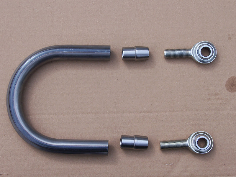
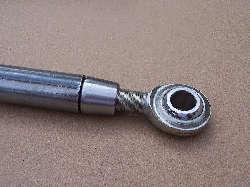
Note to self: Even when buying Aurora rod ends, spend the extra money for the HD units. The CM's are loose out of the box. Basically .001 or so perceptible play, but zero rotation torque... I suspect these will need to be replaced with higher end units after relatively little drive time.
Forgot:
5/8-18 jam nuts
Sleeves to adapt 5/8" rod ends to 12mm bolt
(McMaster 2868T11 looks likely)
(McMaster 89955K579 also looks likely)
Design dimensions: OD: 0.625, ID (tight) clearance for 0.472, Length 0.750 +.000/-.010
The CM10's are $17 each
The AM10's are $42 each
The XAM8's are $46 each (These have 5/8-18 shank with 1/2" hole in the ball, and would require additional spacing to clamp the pivot tube)
-
The Dark Side of Will
- Peer Mediator
- Posts: 15637
- Joined: Wed Nov 24, 2004 11:13 pm
- Location: In the darkness, where fear and knowing are one
- Contact:
Re: The Mule rides again (sort of) - pics.
Found a couple of leads on the spherical bearing front:
The 850CSi front control arms look like this:

Maybe ZF tech support can get me their part number for the ball joint on the right end.
This is the E31 8 series upper arm with inner ball joint installed. It takes a 12mm bolt and from the photo still looks like ~40mm OD.
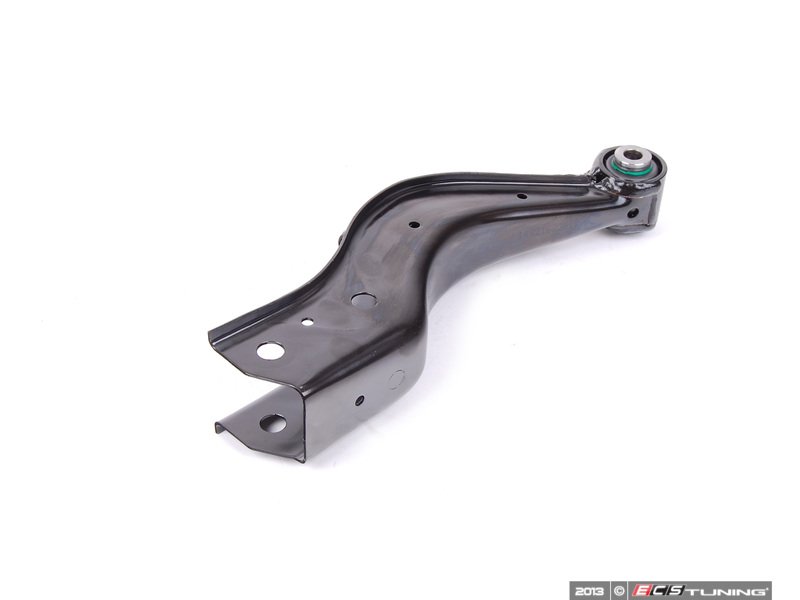
So I guess I need to spend some time on the phone with NHBB on Monday about which of their sealed spherical bearings is appropriate to my application.
Code: Select all
E60 5 series (and many other apps) outer lower:
02	Ball joint		2			33326767748	$63.35
This takes a 16mm bolt
Lemforder PN 1330701 (57.1mm OD... too large, 67.3mm length... too long)

E46 M3 upper & lower outer (Also E36 and others):
02	Ball joint		2			33326775551	$59.70
This takes a 12mm bolt
Lemforder PN 1320801 (45.2mm OD... too large)

E31 850CSi front control arm (ships with ball joint installed):
09	Wishbone, left, aluminum		1		04/1992	31121138477	$309.82
13	Wishbone, left, aluminum		1	04/1992		31121138477	$309.82
This takes a 12mm bolt
Lemforder PN 1309601 (Haven't found a separate listing for the ball joint yet)
Arm with rubber bushing: Lemforder PN 10497 01
Rubber bushing: Lemforder PN 26099 01

E31 850CSi rear lower inner & outer:
02	Ball joint		4			33321135131	$61.11
This takes a 14mm bolt
Lemforder PN 1592701 (OD 41.1mm... also too large)

E31 850CSi rear upper outer:
23	Ball joint		2			33321137819	$80.02
This takes a 14mm bolt
Lemforder PN 1564701 (OD 43.2mm... also too large)

E31 850CSi rear upper arm (ships with inner joint installed)
10	Wishbone		2			33321138015	$292.56
This takes a 12mm bolt
Can't find a Lemforder PN; this may be from a different manufacturer
Maybe ZF tech support can get me their part number for the ball joint on the right end.
This is the E31 8 series upper arm with inner ball joint installed. It takes a 12mm bolt and from the photo still looks like ~40mm OD.
So I guess I need to spend some time on the phone with NHBB on Monday about which of their sealed spherical bearings is appropriate to my application.
The Dark Side of Will wrote:http://www.autopartswarehouse.com/sku/L ... 20774.html
Lemfoerder W0133-1620774
Looks good, but may be too big... I'll have to see if I can get one to try out.

-
The Dark Side of Will
- Peer Mediator
- Posts: 15637
- Joined: Wed Nov 24, 2004 11:13 pm
- Location: In the darkness, where fear and knowing are one
- Contact:
Re: The Mule rides again (sort of) - pics.
Been thinking about how to *realistically* approach killing the engine's oil consumption. It's nice to think about a billet crank but that won't happen for a while.
So I need to take measurements of the journals on the stock crank I have. I've already turned the counterweights down, so the weight relief is done. I need to evaluate whether it will give me the clearances I want with stock size bearings or if I'll need to have it cut and work with undersized bearings. If I have it cut, then I'll need either to install and measure a new set of bearings when the current crank comes out or confirm my measurements on the current bearings. Either way, I can't have it cut until the current crank comes out.
I think the dyno demonstrates that the expensive top rings I bought from Total Seal are doing what they're supposed to be doing.
However, given my problems and the problems that Spec Miata guys have with TS rings and oil consumption, as well as what I've read on SpeedTalk about who TS claims uses their rings vice who *ACTUALLY* uses their rings, I'm starting to think that TS oil rings and maybe 2nd rings as well are crap.
So when the engine comes apart to swap cranks I'll pull pistons and seriously evaluate oil rings.
I'll snag the profilometer from where my dad works to measure what the bore surface finish actually is.
I'll cut apart a spare Y2K block I have to get one of the liners out, then cut the liner apart to measure how hard it is on a local shop's Rockwell tester. The shop my dad works at has a Brinell tester, so I may do both.
I'll have to figure out how to measure ring tension, as well as taking axial and radial thickness measurements of current oil rings to guesstimate ring tension.
Once I have the complete set of hard data, I'll have to spend some time on the phone with TS, Sealed Power and other ring manufacturers to figure out what I can get that will put this problem to bed once and for all.
I also need to get a set of Aurora 4.0 cylinder heads and get started modifying them to accept the Y2K intake manifold.
ALSO...
A few years back a chap took up my suggestion to change the gearing on his 282 to work better on a road course. He was (still is, I assume) a retired mechanical engineer and had the money and expertise to pursue it. He had Houseman Autosport make a new 1-2 input cluster (not the whole input shaft, just a cluster gear similar to the 3-4 output cluster). Houseman also turned the stock gears off the stock synchro hubs, cut new output gears and welded those onto the stock synchro hubs.
He spec'd a press fit for the new cluster onto a modified output shaft. I think he also had Houseman do the work of modifying the input shaft by turning the stock gears down. Knowing that he was a retired mechanical engineer, I @$$umed that he would specify the appropriate radius to use at the inside corner where the modified portion of the shaft met the unmodified portion. Turns out I was wrong.
He built the transmission and installed it beside a ~350 HP supercharged 3800. He said he really liked the gearing on track, but on his 2nd track day he had a trans failure. 1st and 2nd were usable, but 3rd, 4th and 5th were additional neutrals.
He pulled the parts out of the transmission and found that the input shaft had sheared at the sharp corner between the modified OD and the stock OD. Ooops.
He then decided that he was tired of crawling around under a Fiero, bought a Porsche and sold me the gearset at about $.15 on the dollar.
That was 6 years ago and I have it on the shelf.
I've been conflicted about installing it into my transmssion.
The main consideration is the risk of mechanical failure. I'm reasonably sure I can do the shaft mods correctly to prevent the failure mode he experienced, but there's always a risk.
The 2.50 first gear would reduce 1st gear acceleration dramatically, BUT as my current power level puts me almost at the limits of first gear traction now, a taller 1st gear would let me maintain traction while increasing power. I can also go to a Tilton clutch to reduce flywheel losses and increase first gear acceleration.
I had been putting off installing my 3.94 FD and EP "LSD" because I like the 3.50/2.19 gearset in the car now better than the standard 3.50/2.05 set and the 3.50/2.19 set that's in the car is the only one I have... meaning I'd have to pull the trans, tear it down, install the 3.94 and reassemble (with HTOB bellhousing).
If I use the 2.50/1.85 set instead, I have enough parts on the shelf (I *think*... need to verify) to build a complete transmission which I can then swap for the current transmission. I'll end up with multiple spares on the shelf: the current trans AND the trans I originally used with the stock Northstar engine.
For the record, the original trans is a rebuilt stock Fiero unit, only modded to bolt to the Northstar. The current trans has the aforementioned 3.50/2.19 set as well as 1.02 4th gear and Gr8 Grip friction device. It has the stock 3.61 final and .72 fifth. The trans I'm talking about building would be 2.50/1.85/1.38/1.02/0.72 with 3.94 final. With the new combo, 1st will be 28% taller than stock/current, 2nd will be 8.4% taller than current/about 1.5% taller than stock, 3rd will be 8.4% shorter than stock/current, 4th will be 8.4% shorter than current/15.6% shorter than stock, and 5th will be 8.4% shorter than current/stock.
I'll pass on the .81 fifth until I swap to an F40.
Re: The Mule rides again (sort of) - pics.
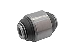
Will an alternative for a sphericial bearing you may want to look into can be found in the rear suspension of a ~05 Hyundai Elantra. Its located in the rear knuckle and is referred to as a Pillow Block Bushing according to Hyundai. I had one apart the other day and didn't even think of measuring it.
.......................
I know the transaxle you speak of well, I performed the drivetrain swap and installed that transaxle twice. It would be unfair to suggest the owner was at fault for why the transaxle failed as it did. The job was sourced out to a shop called The Transmission Man located at 300 Exeter Rd London Ontario ( I still have a scan of the shipping label when I sent it back for re-engineering).
They were send both the original 282 and also Quad 4 282 gearsets. They performed all the work as per specified as far as gear sets / ratio's were required. They fully assembled the transaxle and shipped it back. The first time it was somewhat of a failure, it would not shift into 1st gear, it would jump out of second. We transferred the car to my shop where I removed the complete transaxle and send it back to Ontario. Being the owner had just spent over 3 large on having it built I did not crack the case to see what was wrong. For that kinda moolah it should just work right the first time.
We were told that the press fit 1-2 gear set needed to be recreated as it's dimensions were off to allow sufficient movement of the synchronizer sleeve to properly engage the gear's. So the original press fit gear set had to be removed and a second group installed. What kind of stresses that put the machined, now undersized original input shaft under I do not know, That may or may not have contributed to the failure.
When it came back the second time it worked and worked well. I cannot recall exactly the shift points because that was 8 years ago now, but it seem to keep the engine continually in the power band. Was the gearing perfect for a 3800? I do not know but I do know it was pretty fucking good, the best gear ratio's I ever pulled through, and I drove that car hard for a solid month trying to break it ( customers request ).
That transaxle did see a couple dyno pulls, It did a couple 1/4 mile runs, it was autocrossed 3 or 4 times. It spend a day hot lapping at Mosport Park and then on the second day it failed and you know the rest of the story.
When he contacted me and told me about it he was somewhat annoyed that it had failed for that specific reason, he could not understand why the builder failed to properly relief where they undersized and stepped the input shaft. How much of the engineering did he put into it, I don't know But I can tell you he worked at the head of some of the bigger corporations and also had friends at SLP Engineering that gave their input on it. I would think that if it he and his friends specified every detail, then the builder failed to heed direction. In the end the builder should have known this anyway regardless.
Poor bugger, shortly after he got that Porsche he called me one day and said the motor blew up in that and all of a sudden 20k Fiero builds didn't seem so out of wack.
EDIT:
Perhaps you are correct that a certain place actually did the gearset fabrication and machining, Now that I've thought about it more, that transmission shop was subleted to do the assembly R&R
Here's that gear set all fresh and minty, this is the first set that didn't shift properly.

Here's how you received them

.......................
I know the transaxle you speak of well, I performed the drivetrain swap and installed that transaxle twice. It would be unfair to suggest the owner was at fault for why the transaxle failed as it did. The job was sourced out to a shop called The Transmission Man located at 300 Exeter Rd London Ontario ( I still have a scan of the shipping label when I sent it back for re-engineering).
They were send both the original 282 and also Quad 4 282 gearsets. They performed all the work as per specified as far as gear sets / ratio's were required. They fully assembled the transaxle and shipped it back. The first time it was somewhat of a failure, it would not shift into 1st gear, it would jump out of second. We transferred the car to my shop where I removed the complete transaxle and send it back to Ontario. Being the owner had just spent over 3 large on having it built I did not crack the case to see what was wrong. For that kinda moolah it should just work right the first time.
We were told that the press fit 1-2 gear set needed to be recreated as it's dimensions were off to allow sufficient movement of the synchronizer sleeve to properly engage the gear's. So the original press fit gear set had to be removed and a second group installed. What kind of stresses that put the machined, now undersized original input shaft under I do not know, That may or may not have contributed to the failure.
When it came back the second time it worked and worked well. I cannot recall exactly the shift points because that was 8 years ago now, but it seem to keep the engine continually in the power band. Was the gearing perfect for a 3800? I do not know but I do know it was pretty fucking good, the best gear ratio's I ever pulled through, and I drove that car hard for a solid month trying to break it ( customers request ).
That transaxle did see a couple dyno pulls, It did a couple 1/4 mile runs, it was autocrossed 3 or 4 times. It spend a day hot lapping at Mosport Park and then on the second day it failed and you know the rest of the story.
When he contacted me and told me about it he was somewhat annoyed that it had failed for that specific reason, he could not understand why the builder failed to properly relief where they undersized and stepped the input shaft. How much of the engineering did he put into it, I don't know But I can tell you he worked at the head of some of the bigger corporations and also had friends at SLP Engineering that gave their input on it. I would think that if it he and his friends specified every detail, then the builder failed to heed direction. In the end the builder should have known this anyway regardless.
Poor bugger, shortly after he got that Porsche he called me one day and said the motor blew up in that and all of a sudden 20k Fiero builds didn't seem so out of wack.
EDIT:
Perhaps you are correct that a certain place actually did the gearset fabrication and machining, Now that I've thought about it more, that transmission shop was subleted to do the assembly R&R
Here's that gear set all fresh and minty, this is the first set that didn't shift properly.
Here's how you received them
-
The Dark Side of Will
- Peer Mediator
- Posts: 15637
- Joined: Wed Nov 24, 2004 11:13 pm
- Location: In the darkness, where fear and knowing are one
- Contact:
Re: The Mule rides again (sort of) - pics.
That looks familiar 
Thanks for the info! I did not know you were involved with the project at the time.
What I gathered from the emails I received was that the 1-2 shift collar wasn't properly relieved to fit inside the smaller 1st output gear, which is why it wouldn't go into first the first time. I'd had a gear expert in New Orleans look at the 1st and 2nd gear sets before, and he said that no tooling could make the 1st output gear from a single piece of steel, and that it was probably friction welded (or maybe just pressed?) together from a hub with the synchro cone and shift collar splines and a ring with the gear teeth. The gear teeth overhang the synchro splines, so it couldn't be made from one piece AND the shift collar slips inside the gear to engage first. In welding on the new gear, Houseman just didn't think about modifying the shift collar as well.
I remember hearing that Houseman wasn't too happy with the amount of work he ended up sinking into that project for what he charged.
It's good to hear that Rick understood the need for a radius there. We may have both @$$umed that the guy running the lathe knew about that also.
It's also good to hear it lasted through a good bit more abuse than I heard about.
I thought at the time that getting a Porsche for a trouble-free track car was a better idea than trying to make a Fiero do that. Then I found out about IMS bearings...
What I am planning is to bore the 2nd gear side of the cluster such that the wall thickness under the minor diameter of the gear is the same as the wall thickness under the minor diameter of 1st gear, as well as putting a generous chamber at the edge. I'll have the shaft turned down to the 1st gear diameter with a taper to the 2nd gear diameter, with an appropriate press fit. If the machinist and I are feeling good about it, we may try to taper-lock the ID taper inside the cluster gear to the OD taper on the shaft. The largest radius I can fit on the shoulder where the shaft is turned down will snuggle in under the chamber on the modded cluster gear.
I was able to find some email traffic on it in my archive:
Now that I looked through my email archive, I see that he did mention your involvement.
I think that with the changes I intend to make, it should be pretty durable. Plan B is to call Houseman back and have him make a completely new input shaft... but that'll probably be $2000.
Do you have a Hyundai part number or a parts diagram showing that pillow block?
Thanks for the info! I did not know you were involved with the project at the time.
What I gathered from the emails I received was that the 1-2 shift collar wasn't properly relieved to fit inside the smaller 1st output gear, which is why it wouldn't go into first the first time. I'd had a gear expert in New Orleans look at the 1st and 2nd gear sets before, and he said that no tooling could make the 1st output gear from a single piece of steel, and that it was probably friction welded (or maybe just pressed?) together from a hub with the synchro cone and shift collar splines and a ring with the gear teeth. The gear teeth overhang the synchro splines, so it couldn't be made from one piece AND the shift collar slips inside the gear to engage first. In welding on the new gear, Houseman just didn't think about modifying the shift collar as well.
I remember hearing that Houseman wasn't too happy with the amount of work he ended up sinking into that project for what he charged.
It's good to hear that Rick understood the need for a radius there. We may have both @$$umed that the guy running the lathe knew about that also.
It's also good to hear it lasted through a good bit more abuse than I heard about.
I thought at the time that getting a Porsche for a trouble-free track car was a better idea than trying to make a Fiero do that. Then I found out about IMS bearings...
What I am planning is to bore the 2nd gear side of the cluster such that the wall thickness under the minor diameter of the gear is the same as the wall thickness under the minor diameter of 1st gear, as well as putting a generous chamber at the edge. I'll have the shaft turned down to the 1st gear diameter with a taper to the 2nd gear diameter, with an appropriate press fit. If the machinist and I are feeling good about it, we may try to taper-lock the ID taper inside the cluster gear to the OD taper on the shaft. The largest radius I can fit on the shoulder where the shaft is turned down will snuggle in under the chamber on the modded cluster gear.
I was able to find some email traffic on it in my archive:
And he was right about the press... that's not what failed.Rick wrote: Based on the OEM shrink fits, which are in the 0.0015 to 0.003" range, I am confident that the proposed 1st-2nd combo gear will do the job.
FYI, the corresponding Getrag bores under 3rd and 4th are 1.6537" and 1.6544 respectively.
Now that I looked through my email archive, I see that he did mention your involvement.
I think that with the changes I intend to make, it should be pretty durable. Plan B is to call Houseman back and have him make a completely new input shaft... but that'll probably be $2000.
Do you have a Hyundai part number or a parts diagram showing that pillow block?
Re: The Mule rides again (sort of) - pics.
The Dark Side of Will wrote: Do you have a Hyundai part number or a parts diagram showing that pillow block?
Try this link, it's part # 5 Listed as a balljoint here
http://stores.revolutionparts.com/hyund ... y=10564605
-
The Dark Side of Will
- Peer Mediator
- Posts: 15637
- Joined: Wed Nov 24, 2004 11:13 pm
- Location: In the darkness, where fear and knowing are one
- Contact:
Re: The Mule rides again (sort of) - pics.
I don't guess you have an old one around, just to measure the shell OD?
PN is 55130 4D000.
EDIT: http://www.autopartoo.com/oem/hyundai/551304D000.html
Cross reference among different aftermarket manufacturers.
Edit again:
No reason I can't get the $11 rubber bushing to measure in lieu of the $50 ball joint.
PN is 55130 4D000.
EDIT: http://www.autopartoo.com/oem/hyundai/551304D000.html
Cross reference among different aftermarket manufacturers.
Edit again:
No reason I can't get the $11 rubber bushing to measure in lieu of the $50 ball joint.
Re: The Mule rides again (sort of) - pics.
Actually I didn't replace it, the dealer didn't have one in stock and was looking at a week to get one. Seeing the bushing in that car was a bit tight and noisy I just lubed it with Fluid Film and put it back together. If the customer does return and want it replaced I will most certainly measure it for you.
-
The Dark Side of Will
- Peer Mediator
- Posts: 15637
- Joined: Wed Nov 24, 2004 11:13 pm
- Location: In the darkness, where fear and knowing are one
- Contact:
Re: The Mule rides again (sort of) - pics.
Do you remember what size the bolt is?
EDIT: Notepad: http://www.ronmorrisperformance.com/01hot_new/
EDIT: Notepad: http://www.ronmorrisperformance.com/01hot_new/
-
The Dark Side of Will
- Peer Mediator
- Posts: 15637
- Joined: Wed Nov 24, 2004 11:13 pm
- Location: In the darkness, where fear and knowing are one
- Contact:
Re: The Mule rides again (sort of) - pics.
Minor victory: I have my PCV system fully sealed now.
When I installed to the OBDII throttle to go with the Shelby computer, I had to change to the OBDII PCV tubes. The OBDII fresh air tube connects to the throttle so that it draws metered air (been through the MAF) into the PCV system. The OBDI fresh air tube connected to the intake boot. Both tubes go to the same location on the forward cam cover. The formed nylon tube is the same diameter between the OBDI and OBDII styles. However, the OBDII assembly has a larger diameter fitting at the connection to the cam cover. The OBDII grommet designed for this larger fitting requires a larger hole in the cam cover. I didn't know that at the time, so when I tried to put everything together, it didn't fit. Also at the time I didn't realize that I could just pop the fittings out of the formed nylon tubes and swap them, so as to run the OBDI fitting in the OBDII tube. I put it together without a grommet, with just a little bit of a gap around the fitting. I lost track of the OBDI grommet, too, naturally.
I later realized that this was a metered air leak. I had to get a new grommet, which between the higher cost of NOS parts and exorbitant shipping ended up costing me $30. I installed the old fitting in the new tube and put everything back together, so now I eliminated a metered air leak that was affecting my idle BLM's. (Edit: Grommet PN 3533048)
Major work: Just replaced the oil manifold plate and swapped windage tray, main bolts and oil pickup tube to new style design; side effect: ~8 oz of weight savings
I'd been noticing oily deposits accumulating on the outside of the block. After inspection and consideration, I decided that the oil manifold plate on the bottom of the lower crank case was leaking. When I assembled the engine, I modified and then reinstalled a used oil manifold plate, not knowing at the time that pretty much all the gaskets on the engine are one-time-use. I decided that it wouldn't be a big deal to install a stock oil manifold plate, and use the mods I did to the one in the engine as a template for making a better one from scratch.
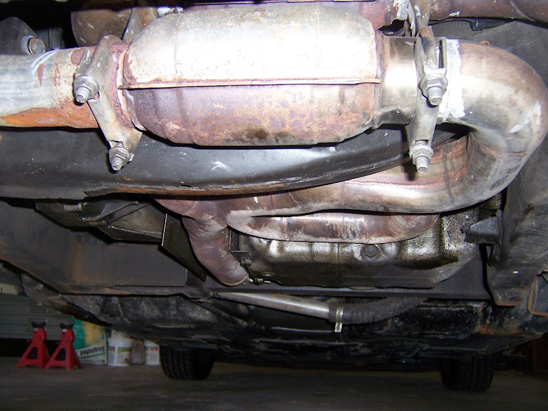
Without further ado:
The bottom of the car after a few thousand miles of driving... the exhaust is much dirtier than the last photo I took.
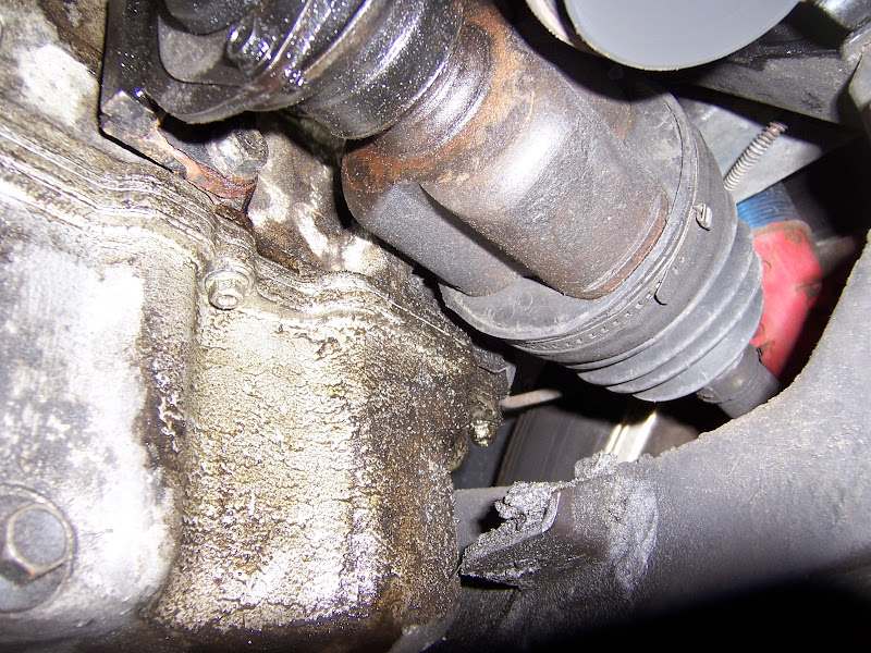
Oil schmutz on intermediate shaft and right inner CV joint:

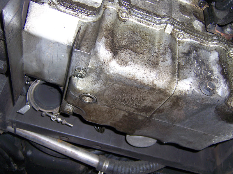
OIl stains with exhaust removed:

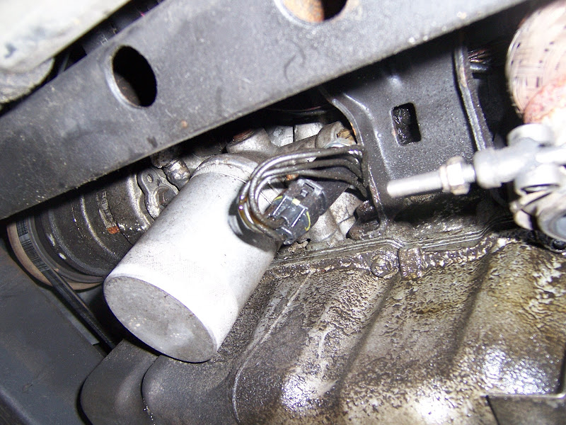
Closer view, can also see the remainder of the stock Fiero engine mount "tray":
The front side of the block:
More schmutz:
Old style setup with oil pan removed and crank pulley blocked up on 2x4's; the front of the engine needs to come up a couple of inches to reach the front oil pan bolts

Windage tray removed:

New parts ready to go in:
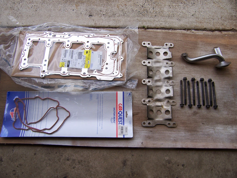
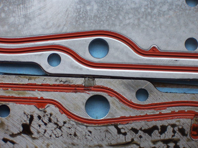
Overall comparison of the manifold plates; the grey "ring" on the old one is oil resistant RTV I used to seal the new style pickup tube to the old style plate which didn't have the built-in seal:
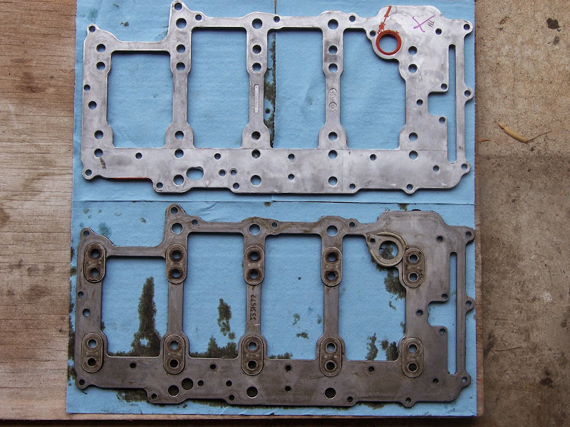
Here's the big difference. The old style had cast-in-place steel bucks against which the main bolts tighten. The new style plate doesn't have those. Instead the main bolts tighten against the steel windage tray
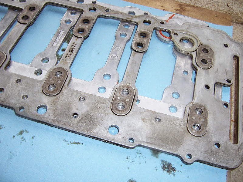
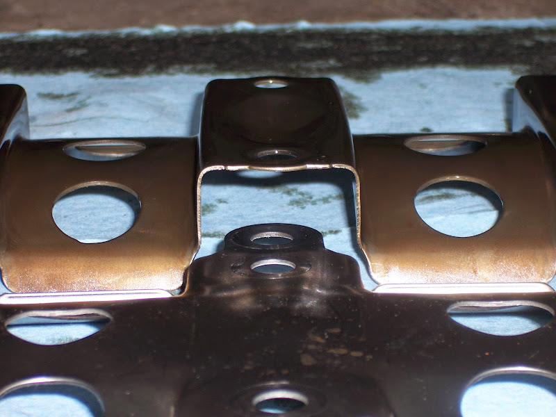
The biggest mod I made to the old one; this is an oil drain back hole. These holes are cored in the lower crank case, so they taper, small end at the bottom. They can be drilled out (one had to be located on a mill, though), but then the holes in the manifold plate need to be opened up also:
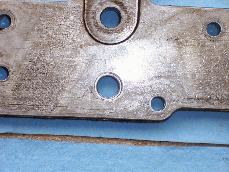
Here's why it's ticklish:
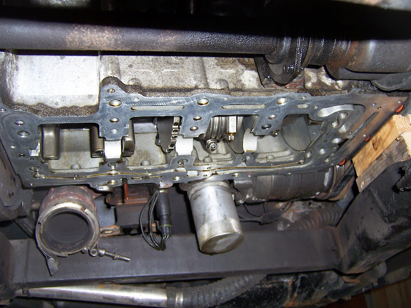
Lower crank case with the manifold plate removed:
Comparison of the detail differences between the windage trays:
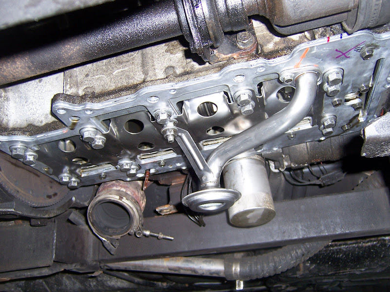
New hardware installed
The parts that came out; I saved the weight of the nuts, the stud heads on the bolts and a few grams out of the windage tray:

Also had a realization about my oil consumption... I need to dig out my invoice from Total Seal and have a discussion with them. If I used low tension oil rings, those in combination with my large bearing clearances could certainly explain my oil consumption. At the time I didn't realize (or maybe just didn't connect the dots) that low tension rings require exquisite crankcase oil control.
Also, looking at options for intake and throttle body upgrades.
I *think* that later in the production run, the Northstar and LS engines started to use the same throttles.
Does anyone know what a 12555840 does? It looks like an adapter coupling that bolts to the LS 3 bolt throttle connection, but the other side looks like it just takes a round tube...
When I installed to the OBDII throttle to go with the Shelby computer, I had to change to the OBDII PCV tubes. The OBDII fresh air tube connects to the throttle so that it draws metered air (been through the MAF) into the PCV system. The OBDI fresh air tube connected to the intake boot. Both tubes go to the same location on the forward cam cover. The formed nylon tube is the same diameter between the OBDI and OBDII styles. However, the OBDII assembly has a larger diameter fitting at the connection to the cam cover. The OBDII grommet designed for this larger fitting requires a larger hole in the cam cover. I didn't know that at the time, so when I tried to put everything together, it didn't fit. Also at the time I didn't realize that I could just pop the fittings out of the formed nylon tubes and swap them, so as to run the OBDI fitting in the OBDII tube. I put it together without a grommet, with just a little bit of a gap around the fitting. I lost track of the OBDI grommet, too, naturally.
I later realized that this was a metered air leak. I had to get a new grommet, which between the higher cost of NOS parts and exorbitant shipping ended up costing me $30. I installed the old fitting in the new tube and put everything back together, so now I eliminated a metered air leak that was affecting my idle BLM's. (Edit: Grommet PN 3533048)
Major work: Just replaced the oil manifold plate and swapped windage tray, main bolts and oil pickup tube to new style design; side effect: ~8 oz of weight savings
I'd been noticing oily deposits accumulating on the outside of the block. After inspection and consideration, I decided that the oil manifold plate on the bottom of the lower crank case was leaking. When I assembled the engine, I modified and then reinstalled a used oil manifold plate, not knowing at the time that pretty much all the gaskets on the engine are one-time-use. I decided that it wouldn't be a big deal to install a stock oil manifold plate, and use the mods I did to the one in the engine as a template for making a better one from scratch.
Without further ado:
The bottom of the car after a few thousand miles of driving... the exhaust is much dirtier than the last photo I took.
Oil schmutz on intermediate shaft and right inner CV joint:
OIl stains with exhaust removed:
Closer view, can also see the remainder of the stock Fiero engine mount "tray":
The front side of the block:
More schmutz:
Old style setup with oil pan removed and crank pulley blocked up on 2x4's; the front of the engine needs to come up a couple of inches to reach the front oil pan bolts
Windage tray removed:
New parts ready to go in:
Overall comparison of the manifold plates; the grey "ring" on the old one is oil resistant RTV I used to seal the new style pickup tube to the old style plate which didn't have the built-in seal:
Here's the big difference. The old style had cast-in-place steel bucks against which the main bolts tighten. The new style plate doesn't have those. Instead the main bolts tighten against the steel windage tray
The biggest mod I made to the old one; this is an oil drain back hole. These holes are cored in the lower crank case, so they taper, small end at the bottom. They can be drilled out (one had to be located on a mill, though), but then the holes in the manifold plate need to be opened up also:
Here's why it's ticklish:
Lower crank case with the manifold plate removed:
Comparison of the detail differences between the windage trays:
New hardware installed
The parts that came out; I saved the weight of the nuts, the stud heads on the bolts and a few grams out of the windage tray:
Also had a realization about my oil consumption... I need to dig out my invoice from Total Seal and have a discussion with them. If I used low tension oil rings, those in combination with my large bearing clearances could certainly explain my oil consumption. At the time I didn't realize (or maybe just didn't connect the dots) that low tension rings require exquisite crankcase oil control.
Also, looking at options for intake and throttle body upgrades.
I *think* that later in the production run, the Northstar and LS engines started to use the same throttles.
Does anyone know what a 12555840 does? It looks like an adapter coupling that bolts to the LS 3 bolt throttle connection, but the other side looks like it just takes a round tube...
-
ericjon262
- Posts: 2843
- Joined: Mon May 24, 2010 5:34 pm
- Location: Aiken, SC
Re: The Mule rides again (sort of) - pics.
so if I'm looking at this right, the new windage tray is deeper and "hugs"the crank closer? stock later model part or aftermarket?
"I am not what you so glibly call to be a civilized man. I have broken with society for reasons which I alone am able to appreciate. I am therefore not subject to it's stupid laws, and I ask you to never allude to them in my presence again."
-
The Dark Side of Will
- Peer Mediator
- Posts: 15637
- Joined: Wed Nov 24, 2004 11:13 pm
- Location: In the darkness, where fear and knowing are one
- Contact:
Re: The Mule rides again (sort of) - pics.
They're the same distance from the crank, but the new one mounts under the heads of all 20 main bolts, while the old one mounts on top of the heads of 10 stud headed bolts.
It's a little hard to see without looking at back-to-back pics.
It's a little hard to see without looking at back-to-back pics.
The Dark Side of Will wrote: Old style setup with oil pan removed and crank pulley blocked up on 2x4's; the front of the engine needs to come up a couple of inches to reach the front oil pan bolts
New hardware installed
-
ericjon262
- Posts: 2843
- Joined: Mon May 24, 2010 5:34 pm
- Location: Aiken, SC
Re: The Mule rides again (sort of) - pics.
10-4 the pic explains everything.
"I am not what you so glibly call to be a civilized man. I have broken with society for reasons which I alone am able to appreciate. I am therefore not subject to it's stupid laws, and I ask you to never allude to them in my presence again."
-
The Dark Side of Will
- Peer Mediator
- Posts: 15637
- Joined: Wed Nov 24, 2004 11:13 pm
- Location: In the darkness, where fear and knowing are one
- Contact:
Re: The Mule rides again (sort of) - pics.
"Oetiker" clamps are basic CV joint boot clamps...
http://www.oetiker.com/en/Solutions/Vehicle-Industry
Audi likes these a lot for engine bay hardware.
Also, now that I've dealt with the oil manifold plate, the next purchase I make for it before pulling the engine to tear it down to address the bearing clearance and ring tension will be an oil cooler.
Rerererererererere-posting the updated links for the coolers I've wanted forever:
Oil cooler: http://www.marineengineparts.com/catalo ... gory/7751/
Oil + trans fluid cooler: http://www.marineengineparts.com/catalo ... gory/7751/