Page 1 of 25
custom intake for 3.4dohc turbo
Posted: Tue Oct 18, 2005 11:58 am
by Kohburn
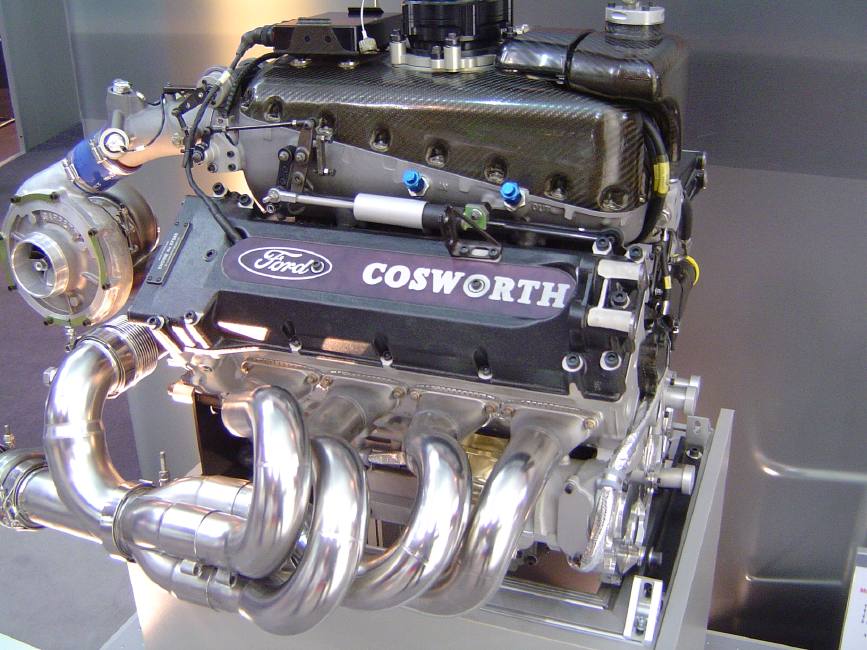
this picture, along with hating GM for making a coolant passage through the plenum that is sealed to the lower intake with an o-ring.. has encouraged me to build a custom clamshell intake for the 3.4..
I will of course have to machine a lower plate out of 1/2" aluminum to mate to the lower intake with radiused edges on the top side.. and machine a plate for a new TB to bolt to.. the rest can all be composite - most likely kevlar as i have a few yards of it sitting around wanting to be used.
suggestions for TB?
Posted: Tue Oct 18, 2005 2:13 pm
by Kohburn
found something to help show what I have planned.. something similar to this except the intake box would be mirrored about the centerline of the runners, and there of course will be 6 runners
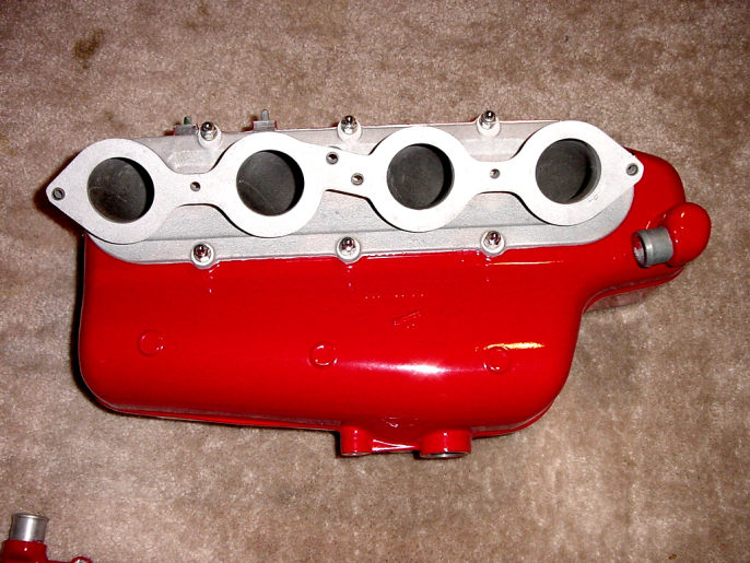
with most of the volume being off to the sides of the runners and the TB centered at the end
Posted: Tue Oct 18, 2005 2:48 pm
by Kohburn
something like this - just enough rise to clear the injectors and narrow enough to clear the valve covers - with a proper taper front to back to encourage even airflow (5 minutes of CAD work)

Posted: Tue Oct 18, 2005 5:13 pm
by donk_316
build me one also.
Posted: Tue Oct 18, 2005 6:03 pm
by Shaun41178(2)
do it up man. sheetmetal intake would look sweet.
Posted: Tue Oct 18, 2005 6:31 pm
by Series8217
I have an idea for the same thing floating around in my head for awhile. I love the idea of a composite intake but also figured I don't really have the skill to pull it off right now. Depending on how well yours turns out maybe I'll give it a try.
My plan was to cut apart the lower intake maniold so that its just left with the flanges and injector holes. The composite plenum would bolt to the flanges and the fuel rail would be INSIDE the plenum cover. If necessary it could be covered by an internal piece to prevent fuel from sitting in the manifold if the rail leaks. It would suck to have the thing explode if it backfired on startup.
I wanted it to be so low for hood clearance, ease of access to the valve covers to play around with cam timing, and of course sleek appearance. I would probably have to use a smaller plenum area due to the practically nonexistent runners though. I don't want it tuned for 9k rpm!
AFAIK the LS1 and LT1 throttle bodies use the same sensors as the 3.4 DOHC. They should be plug'n'play.
Posted: Tue Oct 18, 2005 8:25 pm
by eHoward
It can be done. You've got access to machine equipment. You can make a nice mold from tooling foam or aluminum. I wouldn't use kevlar but that's me.
Posted: Tue Oct 18, 2005 9:18 pm
by Aaron
Series8217 wrote:
AFAIK the LS1 and LT1 throttle bodies use the same sensors as the 3.4 DOHC. They should be plug'n'play.
Most every GM throttle body will be plug and play, and I think a 70-75mm unit would be best for his power levels, and that leaves a lot of options.
As for the intake, DO IT! I'd replace the LIM as well, but I can understand your reasoning for not. As for the coolant lines. The bore for coolant to travel up to the UIM is for the throttle body, and it can be blocked off, but if you remember the discussion we had over at Old Europe, you may want to leave it to bypass the heater core and thermostat for when the motor is cold. But that leaves a problem in connecting it. It cannot really be tapped, I tried that, and I doubt mine will seal well. My only idea would be to weld a nipple on, then slide rubber lines on, or just weld aluminum lines to run coolant through. Other than this the coolant is pretty straight forward.
You also may want to look into a 96-97 LIM. It features all 6 ports in a straight line, so it'd make tooling easier. The coolant situation would also be a bit easier, but not much. It has 2 bores on the side, one for the thermostat bypass/heater core return, the other for throttle body/heater core feed. Kinda confusing, but if you want me to go into it further I will. Essentially you have 2 bores, 1 for heater core, 1 for thermostat bypass. But the T-stat bypass also functions as a place for the heater core return to dump into. These are smooth bores, I had to drill them and tap them for my swap, the factory setup relies on the throttle body to push them in and seal them, so you will probably need to tap them if going this route.
Other than this it should be pretty straight forward, make sure to get an appointment with Darth or Ben afterwards to get it tuned. Also, be sure to port/polish/match the LIM. Since you're boosted, open them up as much as you can.
Lots of pictures are a must. If there is anything I can do, let me know.
Here is Serie's photoshop of an LT1-like intake on his LQ1:

Posted: Wed Oct 19, 2005 7:36 am
by Kohburn
picked up a intake gasket set yesterday and i'm going to talk to my shop guys today about having them cutting out a base plate using the gasket as the pattern..
next i will need to pick up a TB from the JY to clean up and use as a pattern for cutting the intake end plate..
the plan after that is to weld the base and end plate together then cover them in plastic and spray up a big blob of expanding foam.. carve that back down and glass it in - then cut that open to remove the foam... a little finish work with high temp epoxy (I can get stuff good for up to 4000*) including bonding in some threaded sleeves to screw the top half back on with
Posted: Wed Oct 19, 2005 9:10 am
by The Dark Side of Will
Whip up a set of sliding throttles to go between the new plenum and LIM.
Posted: Wed Oct 19, 2005 9:18 am
by Kohburn
The Dark Side of Will wrote:Whip up a set of sliding throttles to go between the new plenum and LIM.
sliding throttles?
side note - since i can get resins good for up to 4000* I could actually make a metal casting mold and make the intake from cast aluminum.
I'd just have to build a small foundry and melt down some aluminum (maybe some fiero parts)
Posted: Wed Oct 19, 2005 9:26 am
by The Dark Side of Will
Sliding plates as opposed to butterfly valves.
For a given orifice size, sliding throttles have less restriction than butterfly.
Posted: Wed Oct 19, 2005 9:39 am
by Kohburn
The Dark Side of Will wrote:Sliding plates as opposed to butterfly valves.
For a given orifice size, sliding throttles have less restriction than butterfly.
at WOT - but at partial throttle plate perpendicular to the airflow creates a lot of turbulence
if i want less restriction i can just use a bigger TB
does the northstar use the same sensors as the 3.4 int he TB?
Posted: Wed Oct 19, 2005 10:09 am
by The Dark Side of Will
'96 and later.
Configure the sliders to open so that at part throttle the open side is the same side as the injector/port roof.
Posted: Wed Oct 19, 2005 10:40 am
by Kohburn
ok so a 96+ northstar TB
since the casing is not structural (due to the machined baseplate and TB plate), I'll most likely forego the kevlar and just cast it from aluminum urethane which is good to 250* and still about 5000psi tensile strength
its even machinable so i could polish it up to match the valve covers if i didn't want to paint it.
my only concern with the aluminum urethane is the low temp, but when is the last time you boiled water on your intake manifold? the next step would be a silica ceramic casting which is good to 2700* and a good thermal insulator but only 1500psi tensile strength
Posted: Wed Oct 19, 2005 10:56 am
by Mach10
Rice-paper... Honda's been doing it for years! :thumbleft:
Actually, why not look into what Toyota's been using for a couple of years on their intake runners... Some sort of high-temp rigid plastic... I know nothing else about it, but you could make some killer runners (with no casting marks) if you built a 2-peice properly.
Plus, it'd be easy to stamp out a couple dozen at a time if you found a plastics manufacturer. :thumbleft:
Posted: Wed Oct 19, 2005 1:12 pm
by Kohburn
ok i located a northstar TB for 38$ and grabbed some 1/4" aluminum plate to mill the base out of.
as for the coolant bypass.. current plan is to block it off to test for any pressure issues.. the thermostat is drilled to allow the system to bleed air out of the engine (had a problem with that before) so it will aleviate some of the pressure. if there are no problems then i'm just going to permanently block it off. otherwise i'll weld a flange over the hole with the 1/2" npt fitting
if i don't putz around then i may be able to have this done in a week and finally get some road data logs to really start tuning
Posted: Wed Oct 19, 2005 1:19 pm
by The Dark Side of Will
What CAD program is that?
Posted: Wed Oct 19, 2005 1:24 pm
by Kohburn
The Dark Side of Will wrote:What CAD program is that?
thats Pro Engineer Wildfire.. its what i used mostly at my current job - I also have solidworks and inventor for 3d along with autocad and turbocad for 2d
Posted: Wed Oct 19, 2005 1:25 pm
by Aaron
Kohburn wrote:ok i located a northstar TB for 38$ and grabbed some 1/4" aluminum plate to mill the base out of.
as for the coolant bypass.. current plan is to block it off to test for any pressure issues.. the thermostat is drilled to allow the system to bleed air out of the engine (had a problem with that before) so it will aleviate some of the pressure. if there are no problems then i'm just going to permanently block it off. otherwise i'll weld a flange over the hole with the 1/2" npt fitting
How are you gonna block it off? I'd just JB Weld a dime or two over it personally.
:salute: